The Robot
The robot was originally a teleoperated manipulator. (I call it a robot for brevity, and call the integrated system a rover.) This means that it did nothing on its own, but was controlled remotely by a human operator. JPL originally used it to handle dangerous chemicals for developing rocket fuels. This activity occasionally resulted in explosions, so the robot had to be very rugged. It was controlled from a panel of knobs, connected by a long cable. The operator could sit in a blockhouse, protected from potential blasts, like the picture below.
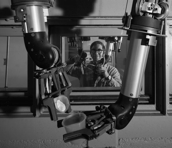
A type of teleoperator used at JPL. This one isn’t on a mobile base, and has a fancier control system than the one I worked with.
The robot stood between four and five feet high at the shoulders. Each of its arms had a shoulder sideways rotation joint, a shoulder elevation joint, an elbow joint, a wrist elevation joint, a hand rotation joint and a two-fingered gripper. All except the gripper were operated by electric motors contained in the large shoulder cylinder. Below each shoulder, the joints were actuated by chain drives (like a small bicycle chain) that ran within the hollow segments of the arm. A special linkage in the drive train kept the attitude of the wrist elevation joint constant as the shoulder and elbow moved. This allowed the operator to lift an open container, and keep it upright, by activating the shoulder or elbow, without having to simultaneously coordinate the wrist motion. (This design feature had nothing to do with my project; I just thought it was clever.)
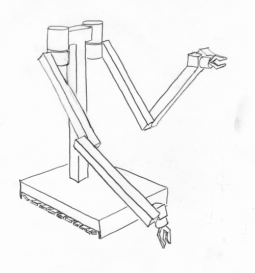
A sketch (all of the sketches and models are from my memory) of the robot as I first saw it.
The gripper was actuated by hydraulic pressure. Everything from the shoulder to the wrist was hollow, sealed, and filled with hydraulic fluid, which also served to lubricate the chain drive. The walls of the shoulder and arm segments were aluminum and steel. The whole thing was painted a light industrial green, except for the joints, which were stainless steel. The arms were attached to a square post that rose from a base. The base was mounted on two tank-like tread drives, mostly shielded from potential explosions. The arms were long enough to reach the ground in front of the base.
The control panel contained a knob for each arm joint, gripper, and track drive. The knobs controlled the speed of the motors, in either direction. Moving a knob further made the corresponding motor run faster. To stop motion of a joint, the operator had to center the knob. Controlling the robot while handling dangerous chemicals must have been quite a challenge.
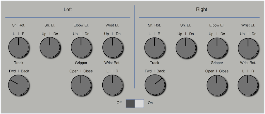
Diagram of the original teleoperator control panel, with the track controls set to pivot the robot to the right. (The left track moves forward and the right track moves backward.)
Joe told me that the control signals were variable-width square waves, in which a narrow pulse width caused slow motion and a wider pulse caused faster motion; positive pulses caused motion in one direction and negative pulses the other. The square waves were not very friendly to the motors, and caused them to get hot when being driven.
I got to play a bit with the control panel, but it was actually not very relevant to our project. Obviously, an operator on Earth can’t control every joint of a robot on Mars, due to the many minutes it takes for control signals to travel to Mars and for video signals and other status to return to Earth, at the speed of light.
Next: Part 5 – The System